Connection - Alphatech (en)


Main menu:
Connection
The Slim IPDP basic module is assembling from modules IP, PoE mudul, camera module and motherboard. Positioning setting elements and connectors are on picture
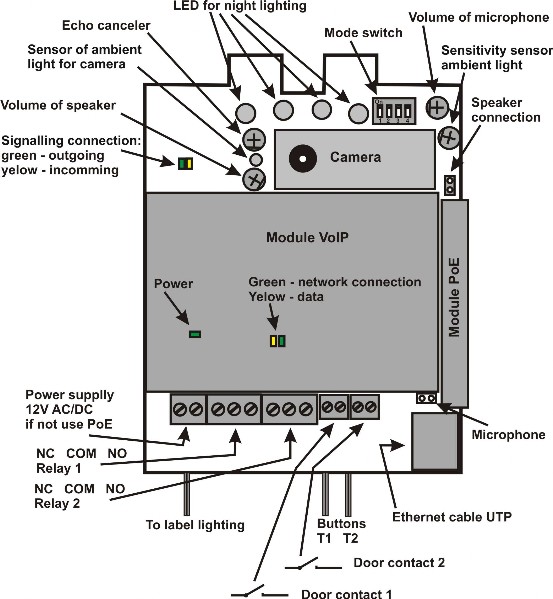
On picture is two inputs for sensors in your IPDP. Door sensors are sensors (eg magnetic contacts or part of electrical lock) to inform the opening / closing doors. Check this option to display the status of the door to the home screen video and sends this information to the program UDVguard where it is displayed. Also information about status of this inputs is displayed on first WEB site with video in WEB browser.
For Slim IPDP is necessary used PoE power from switch or the AC voltage of min. 11Vst - max. 15Vst or DC voltage of min. 12Vss to max. 18Vss must be energized to “12V” terminal. This source loading depends on number of modules, since it simultaneously serves feeding of lighting through visiting cards – at max. number of connected modules the demand will not exceed 300mA. This source can be also used for feeding of lock(s), and then it is necessary to consider the electrical lock demand. In practice the alternating feeder 12V/1A mostly meets these demands.
IPDP receives power through the PoE (Power over Ethernet) technology - IEEE802.3af Altern. A+B. No additional cabling is necessary. If your Ethernet is not equipped with the PoE technology it is possible to use a PoE adaptor. If you use electric lock for opening door, so you must for supply of the lock use power supply (only in circuit with relay - contact), or use low power lock and for supply of the lock use connector on visiting - card (back lighting buttons) and at supply by PoE is here 12V/350mA to disposal.
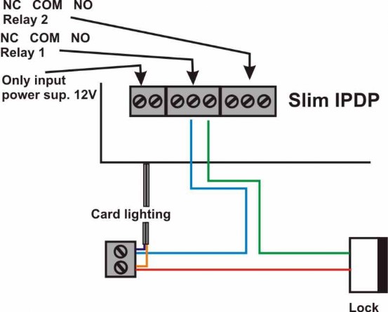
The connection of relay contact terminals is shown on pict. 2. The “NO” designation means an idle-disconnected contact, “COM” means a pin contact (middle) and “NC” means an idle-connected contact. The contacts of both switches are galvanically isolated each other and from other guard circuits. The variants of connection are shown on picture. 3 and 4.
The camera is mounted so that it can be tilted in the vertical direction (up-down) so that optimal image occupy space in front of, or granted for the installation of disabled people.
